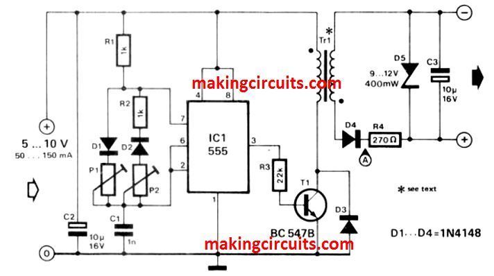
Isolated Dc Dc Converter Circuit Diagram High Current DC to DC Boost Converter Circuit. The following circuit is designed to convert this 5-12 V input to a variable 15-30 V output. The converter is based on a Texas Instruments L497A, which is perfect for building a fly-back circuit. A fly-back converter's switching duration is divided into two phases.

Converter circuit topologies A large number of dc-dc converter circuits are known that can increase or decrease the magnitude of the dc voltage and/or invert its polarity [1-5]. Figure 4 illustrates several commonly used dc-dc converter circuits, along with their respective conversion ratios. In each example, the switch is realized using a power A DC to DC converter is a power electronics circuit that efficiently converts a direct current from one voltage to another voltage. Without a doubt, DC-DC converters play an integral role in modern electronics. This is because they offer several advantages over linear voltage regulators. Linear voltage regulators, in particular, dissipate a lot Types of DC-to-DC Converters 1: Magnetic Converters. In these DC-to-DC Converters, energy is periodically stored and released from a magnetic field in an inductor or a transformer. The frequency ranges from 300 kHz to 10MHz.By maintaining the duty cycle of the charging voltage the amount of power that needs to be transferred continuously to a load can be more easily controlled.
DC to DC Converter Circuit Circuit Diagram
A device's DC-DC converter is allowed to have functional insulation if: - The AC-to-DC power supply uses reinforced or double insulation between the AC input and DC output. - The AC-to-DC power supply uses basic or supplementary insulation, while the secondary circuit of the DC-DC converter connects to protective Earth.
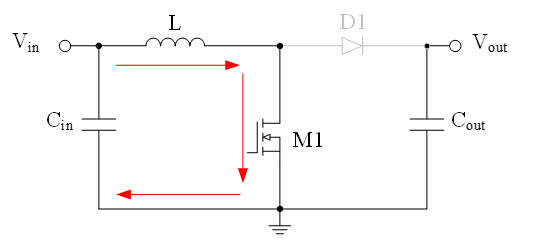
The basic components of the switching circuit can be rearranged to form a step-down (buck) converter, a step-up (boost) converter, or an inverter (flyback). These designs are shown in Figures 1, 2, 3, and 4 respectively, where Figures 3 and 4 are the same except for the transformer and the diode polarity.

DC Converter and How Does It Work? Circuit Diagram
DC to DC Converter Circuit 1. This simple circuit lets you run a 1W LED from the battery of your car. IC MC34063 is used here as a buck converter. It is a monolithic switching regulator sub-system intended for use as a DC-DC converter. The device consists of an internal temperature compensated reference, a comparator, a controlled duty-cycle
